The Easiest Touchscreen Solution



Live Example: Rocket Alumni Solutions Touchscreen Display
Interact with a live example (16:9 scaled 1920x1080 display). All content is automatically responsive to all screen sizes and orientations.
Intent: identify/document. Trophy case LED driver ripple measurement is the process of quantifying the residual AC voltage variation that persists in a constant-current or constant-voltage LED driver’s DC output after conversion from mains power. Every LED driver extracts direct current from alternating current; the conversion is never perfectly clean, and what remains is a cyclic output fluctuation — ripple — that mirrors the mains frequency or its harmonic. On a 60 Hz supply, ripple typically completes 120 cycles per second. At levels above accepted thresholds, that variation modulates the trophy case fixture’s light output at the same frequency, producing the conditions that cause visible flicker to photosensitive visitors, rolling bands in video footage, and color inconsistency across display zones. This guide walks school facilities teams through recognizing the symptoms of high-ripple LED drivers, understanding what the measurement reveals, completing a structured seven-step documentation procedure, and determining when findings require escalation to a qualified electrical installer.
Trophy case corridors at K–12 schools receive more camera traffic than most school spaces. Athletic banquets, senior night ceremonies, championship announcements, yearbook photo sessions, and local news coverage all bring cameras — phone cameras shooting at 60 or 120 frames per second, video crews panning across trophy shelves, and social media content captured under deadline. What none of those cameras tolerate, and what no visual walkthrough of the corridor detects, is LED driver ripple severe enough to modulate fixture output at 100 or 120 cycles per second. The result is rolling dark bands across photos, flickering video that requires correction before it can be published, and a recognition corridor that looks less professional than the awards it holds.
Ripple is an electrical measurement — taken at the driver’s DC output terminals — that quantifies the upstream cause of the light output instability that photometric measurements like Flicker Index and Percent Flicker describe at the fixture level. Facilities teams who understand what ripple is, how to document it safely, and what thresholds require action are better positioned to identify a lighting instability problem before it surfaces at homecoming rather than after.

Trophy case corridors that combine physical cases with digital recognition panels share LED lighting infrastructure — high driver ripple in any fixture zone affects camera performance and visitor experience across the full display environment
What LED Driver Output Ripple Is and Why It Appears
An LED driver converts the AC line voltage from the building’s electrical supply into the DC output the LED module requires. The conversion happens through a rectifier bridge, which inverts the negative half-cycles of the AC waveform, followed by a filter stage — typically electrolytic capacitors — that smooths the resulting pulsed DC into something closer to a steady voltage or current. No filter stage eliminates the AC component completely. What remains is the output ripple: a periodic variation in the driver’s DC output that reflects the original AC frequency or, more commonly, its second harmonic.
On a 60 Hz supply, the rectifier produces pulsations at 120 Hz, and the output ripple following the filter stage typically oscillates at 120 cycles per second. On a 50 Hz supply, ripple appears at 100 Hz. The amplitude of that ripple — how much the DC output voltage or current varies from its average value — is the parameter that determines whether the ripple is benign or problematic.
Why ripple translates directly into light output instability:
LED light output is proportional to the current flowing through the LED junction. A constant-current driver that holds its output current perfectly steady produces steady, flicker-free light regardless of what the rectifier is doing upstream. In practice, the output current of a real driver is not perfectly steady — it varies at the ripple frequency to a degree determined by the quality of the output filter design. A driver with a large, high-quality output capacitor bank produces low ripple and nearly constant LED current. A budget driver with minimal output filtering produces high ripple, and the LED current — and therefore the LED output — rises and falls at 120 Hz accordingly.
Three factors that affect ripple severity in school trophy case installations specifically:
Driver age and capacitor degradation: Electrolytic output capacitors lose capacitance as they accumulate thermal cycles and operating hours. A driver that measured low ripple when installed may produce significantly higher ripple after three or four years in a thermally stressed trophy case enclosure. Capacitor degradation is the dominant ripple-increase mechanism in aging LED drivers.
Enclosed fixture thermal environment: Trophy cases in wood or metal enclosure structures with limited airflow run driver components at higher internal temperatures than the driver’s rated ambient maximum. Elevated temperature accelerates electrolytic capacitor aging, which increases ripple over time. The school trophy case LED heat assessment process at Digital Warming covers the thermal environment audit that informs driver service life predictions — relevant context for interpreting why ripple measurements change between inspection cycles.
Dimming control interaction: Phase-cut (Triac) dimmers, and some 0–10V dimmer implementations at low dim levels, can increase ripple beyond what the driver produces at full output. A driver with acceptable ripple at full brightness may exceed acceptable thresholds when dimmed to 20–30% — the level many trophy case corridors use during non-event hours. Ripple measurements taken at full output only do not characterize driver behavior across the full operating range.
Ripple Measurement Versus Flicker Index: Different Tools, Shared Diagnostic Goal
Two measurement approaches characterize trophy case LED lighting instability. Understanding the difference helps facilities teams know which measurement their situation calls for and which requires a qualified technician.
Output Ripple (Electrical Measurement)
Measured at the driver's DC output terminals using an oscilloscope or a multimeter with AC voltage capability. Ripple voltage is expressed as the RMS value of the AC component at the output, typically reported as a percentage of the DC output voltage. Ripple current measurement — the variation in output current — is the more precise metric but requires a clamp meter with AC current capability and access to the output lead. Output ripple measurement characterizes driver quality and is the upstream cause of light output modulation. It requires safe access to the driver's low-voltage DC output terminals, which a trained facilities technician can perform under the guidance of an electrical professional.
Flicker Index / Percent Flicker (Photometric Measurement)
Measured at the fixture's light output using a calibrated photometric instrument or a high-speed camera analysis. Flicker Index (an IES-defined metric ranging from 0.0 to 1.0) and Percent Flicker (a percentage of the peak-to-trough output swing) characterize how much the light output actually varies at the observer level. These measurements require no access to electrical terminals but do require calibrated instruments or documented high-speed camera procedures. Flicker Index targets below 0.04 and Percent Flicker below 8% at 100–120 Hz are the thresholds associated with the low-risk operating range defined in IEEE PAR 1789-2015 guidance for prolonged-occupancy display lighting.
For school facilities teams without access to calibrated photometric instruments, a structured ripple measurement using a multimeter provides the electrical-side data that informs a qualified installer’s assessment. For teams with access to a smartphone capable of 240 fps video capture, the high-speed video method — panning the camera slowly across the lit trophy case and examining the footage for rolling bands — provides a practical no-instrument screening test that costs nothing beyond the time to record and review the clip.
The options available from most LED fixture or driver suppliers on the trophy display case with lights reference at Touchscreen Website include ripple and flicker specifications in their product data sheets — a starting point for confirming whether the drivers already installed in your trophy case meet published thresholds before any measurement is taken in the field.
Symptoms That Suggest High Driver Ripple
Facilities teams encountering any of the following should add ripple assessment to the maintenance queue for the affected trophy case corridor:
- Video footage with rolling horizontal bands across the trophy case area, reported by yearbook staff, event videographers, or news crews — the most reliable field indicator of ripple-driven flicker at 100 or 120 Hz
- Visitor or staff headache complaints concentrated in or near the trophy case corridor during extended recognition events; photosensitive individuals perceive 100–120 Hz flicker at modulation depths that are invisible to the general population
- Inconsistent brightness between fixture zones in a corridor where all drivers were specified identically — one zone noticeably dimmer or with different apparent color temperature than its neighbors, with no optical explanation such as a different diffuser or lower-wattage LED
- Audible hum from the fixture or driver enclosure at a pitch consistent with 120 Hz — not all driver ripple produces audible noise, but drivers with damaged or aging output capacitors sometimes do
- Progressively degrading display appearance over a 12-to-36-month window in fixtures that looked stable at installation — gradual capacitor aging increasing ripple over time rather than a sudden failure event
Any of these symptoms justifies a documentation procedure before the condition is escalated to a qualified installer for diagnosis and corrective action.
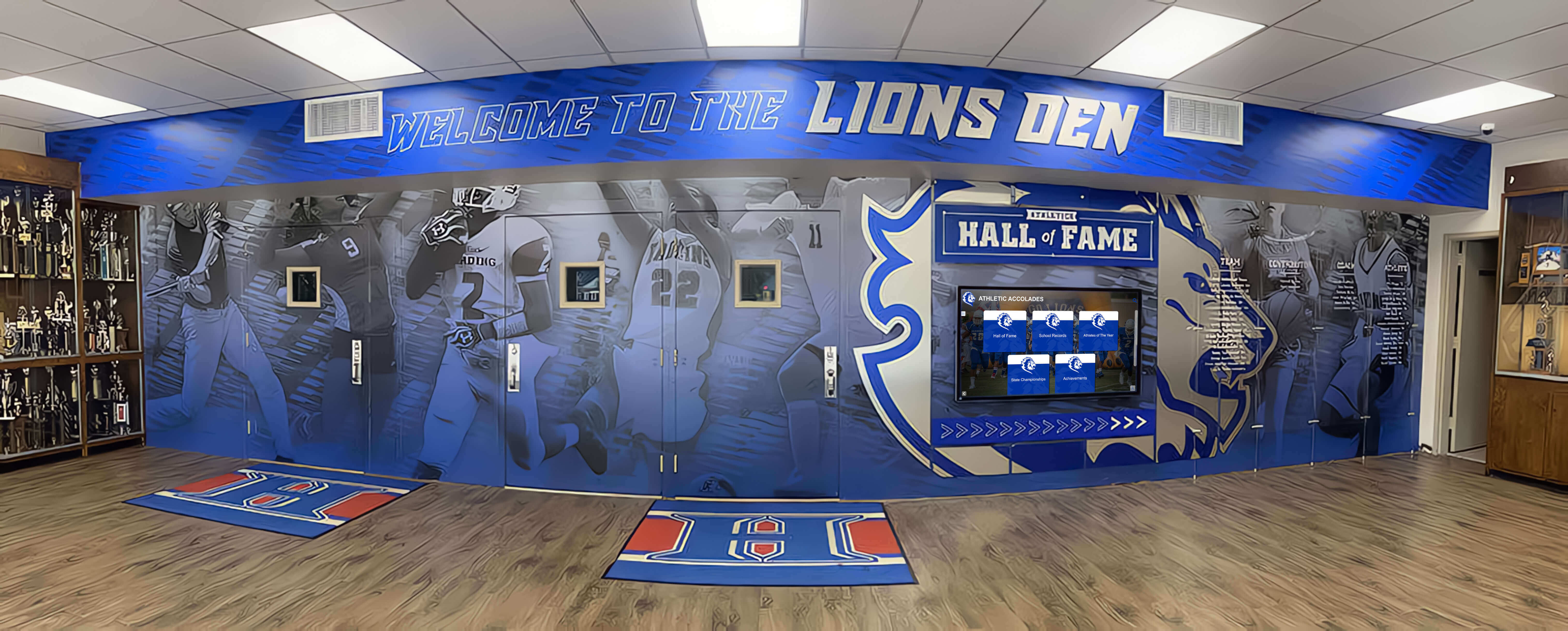
Trophy case corridors with multiple display zones rely on consistent driver output across every position — a single driver producing high ripple creates visible brightness or color inconsistency that disrupts the corridor's unified recognition display
Trophy Case LED Driver Ripple Measurement: Seven-Step Procedure
Steps 1 through 4 are observation and documentation tasks that facilities staff can complete safely. Steps 5 and 6 involve direct contact with driver terminals and require coordination with a licensed electrician or qualified lighting technician. Step 7 is documentation and escalation.
Step 1 — Document the Fixture and Driver Inventory
Before any measurement, compile a fixture map for the affected trophy case corridor:
- Total number of fixture positions and their circuit assignments
- LED driver manufacturer and model number (from the label on each driver, or from installation documentation)
- Driver output rating: DC voltage range and output current in milliamps
- Driver age: installation date from maintenance records, or estimated from the original LED upgrade project
This inventory identifies which drivers are nearing typical service life for electrolytic capacitor-limited components (typically 40,000–50,000 hours at rated ambient temperature, substantially less at elevated temperatures common in enclosed cases), and provides the procurement baseline needed if driver replacement becomes the corrective action.
Step 2 — Request Driver Specifications from the Supplier or Manufacturer
Contact the driver manufacturer or your LED fixture supplier and request the data sheet for the specific driver model installed. On the data sheet, locate:
- Output ripple voltage specification: Expressed in millivolts peak-to-peak (mVpp) or as a percentage of the nominal output voltage. For display-area LED lighting, a commonly referenced guideline is ripple below 5% of the DC output voltage to maintain light output modulation within ranges associated with low flicker risk. Drivers achieving ripple below 1–2% are classified as low-ripple for display-quality applications.
- Output ripple current specification: Some data sheets specify output ripple current in milliamps — the variation in the actual current delivered to the LED string. This metric directly determines light output modulation: a driver delivering 700 mA ± 35 mA produces a 10% current swing at ripple frequency.
- DLC qualification status: DesignLights Consortium Premium qualification requires LED drivers to produce light output with Flicker Index below 0.04 at 100 and 120 Hz under standard test conditions. A DLC Premium-listed driver has been independently tested to meet this threshold; a driver without DLC Premium listing has no independently verified flicker guarantee.
If the driver manufacturer cannot supply a data sheet, or if the installed driver model does not appear in any current product documentation, treat the unit as lacking documented ripple performance and proceed to measurement.
Step 3 — Conduct the High-Speed Video Screening Test
Before any electrical measurement, perform a low-cost preliminary screening using a smartphone capable of 240 frames per second video capture:
- Set the smartphone to 240 fps video mode (available on most current iOS and Android flagships under slow-motion or high-speed video settings)
- Darken the trophy case corridor to the extent possible — close blinds or wait for a low-ambient-light period
- Hold the phone steady and pan slowly across the lit trophy case surface, capturing 10–15 seconds of footage
- Play back the footage at reduced speed and observe the image for horizontal dark bands that scroll vertically through the frame
Rolling bands at 240 fps indicate that the fixture’s light output is modulating faster than the camera’s frame rate can freeze — consistent with ripple-driven flicker at 100–120 Hz. The absence of rolling bands in 240 fps footage does not confirm zero ripple, but it substantially reduces the probability that ripple is producing visible flicker. A positive result (bands present) confirms that photometric instability exists and should be documented and escalated regardless of what electrical measurements show.
Record the screening result — positive or negative — along with the date, the specific fixture positions tested, and the smartphone model and video settings used. This record documents the observation basis for any subsequent corrective action.
Step 4 — Record Environmental Conditions Before Electrical Measurement
Prior to any contact with fixture wiring or driver terminals, document:
- Ambient corridor temperature at the time of measurement (a thermometer placed near the fixture, not a room thermostat reading)
- Dimming level at which the trophy case fixtures are operating — full output, or a reduced dim level — and the control method (manual dimmer, building automation system, scene control panel)
- Whether any fixtures in the corridor have recently been replaced or rewired
Temperature and dimming level affect ripple readings. A driver that tests acceptably at full output in cool ambient conditions may produce elevated ripple at a 25% dim level in a warm enclosure. Document these conditions so that comparison measurements taken at a different time can be correctly interpreted.
Step 5 — Multimeter-Based Ripple Voltage Measurement (Qualified Technician Required)
The following procedure should be completed by a qualified electrician or lighting technician who can safely access driver terminals in a de-energized or appropriately secured fixture enclosure. Facilities staff should not open fixture enclosures containing line-voltage wiring without the direct involvement of a licensed electrician.
Equipment needed:
- True-RMS digital multimeter with AC voltage measurement capability on the millivolt range
- The driver’s DC output polarity from the data sheet or output label (positive and negative terminal identification)
- Personal protective equipment appropriate for work near energized enclosures (insulating gloves rated for low-voltage contact, safety glasses)
Procedure:
- Confirm the fixture is energized and operating at the dim level to be characterized (full output and at the normal dimmed operating level, separately)
- Set the multimeter to AC voltage mode — this measures only the AC component superimposed on the DC output, filtering out the DC level itself
- Touch the multimeter probes to the driver’s positive and negative DC output terminals (or to the output leads at a safe accessible point as directed by the electrician)
- Record the AC voltage reading in millivolts RMS — this is the ripple voltage
- Switch the multimeter to DC voltage mode and record the DC output voltage
- Calculate ripple percentage: (AC ripple voltage RMS ÷ DC output voltage) × 100
Example: A driver with a measured AC ripple of 400 mV RMS on a 24V DC output produces a ripple percentage of 1.67%. A driver showing 2,400 mV RMS AC ripple on the same 24V output produces 10% ripple — a value associated with light output modulation well above the low-risk threshold in IEEE PAR 1789-2015 guidance.
Repeat the measurement at each dim level used during normal corridor operation. Record all readings on the documentation form established in Step 4.
Step 6 — Oscilloscope Waveform Capture (If Available)
A multimeter reading captures the RMS value of the AC ripple component but does not reveal its waveform shape. An oscilloscope connected to the driver’s DC output terminals provides the complete waveform — showing the ripple frequency, peak-to-peak amplitude, and whether the ripple is clean sinusoidal variation or contains higher-frequency spikes indicating filter capacitor degradation.
This step is optional for initial screening but valuable for drivers that produce borderline multimeter readings. A clean ripple waveform at acceptable amplitude suggests a driver that is performing within specification. A waveform with superimposed high-frequency spikes at amplitudes exceeding the ripple baseline indicates a filter component (capacitor or inductor) that has degraded beyond normal aging — a driver condition that should be escalated for replacement rather than accepted as within tolerance.
If oscilloscope capture is not available, the multimeter readings from Step 5 are sufficient to establish pass/review/escalate status using the decision table below.
Step 7 — Document Findings and Establish Escalation Path
Complete a measurement record for each driver tested, including:
- Driver model, serial number if legible, and installation date
- Fixture position identifier (corridor map reference)
- Screening test result (positive or negative for rolling bands at 240 fps)
- DC output voltage measured
- AC ripple voltage measured (RMS, in millivolts)
- Calculated ripple percentage
- Dim level and ambient temperature at time of measurement
- Name and license number of the qualified electrician who performed the electrical measurements
- Date of measurement
Forward the completed record to the licensed electrician or facilities contractor responsible for trophy case maintenance before any corrective action is planned. The measurement record is the basis for the replacement decision, the procurement specification for any replacement driver, and the baseline against which future measurements are compared.
Digital Recognition for Schools: No LED Driver Maintenance Required
While your facilities team documents LED driver ripple in physical trophy cases, Rocket Alumni Solutions can show you how schools are extending their recognition programs with cloud-managed digital displays. Interactive touchscreens with factory-calibrated display hardware, remote content management, unlimited recognition capacity, and WCAG 2.1 AA accessibility — no ripple measurements, no capacitor degradation, and no dark corridor during homecoming because a driver failed silently. See how digital displays complement what your facilities team maintains in the physical cases.
Book A DemoTrophy Case LED Driver Ripple: Decision Table
The following table summarizes the assessment outcomes for each measured parameter and the action each outcome requires. Thresholds reflect published guidance from IEEE PAR 1789-2015 and DLC Premium qualification criteria and should be verified against the specific driver’s data sheet specifications and applicable local requirements.
| Parameter | Pass — No Action Required | Review — Monitor and Re-Test Within 6 Months | Escalate — Qualified Installer Assessment Required |
|---|---|---|---|
| 240 fps video screening | No rolling bands visible across any fixture position | Faint banding visible at low dim levels only | Visible rolling bands at normal operating dim level or full output |
| Ripple percentage (AC ripple ÷ DC output voltage) | Below 5% at all operating dim levels | 5%–10% at any dim level | Above 10% at any dim level, or above 5% at full output |
| DLC Premium listing status | Driver model confirmed DLC Premium listed (Flicker Index < 0.04 independently verified) | Driver is DLC Standard listed but not Premium; ripple measurement required | Driver has no DLC listing or listing cannot be verified |
| Driver age relative to rated capacitor life | Driver is within the first 50% of rated service life at documented operating temperature | Driver is between 50%–80% of rated service life | Driver has exceeded rated service life, or operating temperature suggests accelerated aging |
| Oscilloscope waveform (if captured) | Clean sinusoidal ripple at measured amplitude; no high-frequency spikes | Slight waveform irregularity; ripple frequency consistent with mains harmonic | High-frequency spikes superimposed on ripple baseline; irregular waveform shape indicating component degradation |
| Ripple change from previous measurement | Stable or declining ripple versus prior measurement | Increase of 2–5 percentage points since last measurement | Increase of more than 5 percentage points since last measurement, or driver has never been measured |
| Visitor or staff complaints | No complaints in the past 12 months | Isolated complaints during events; no recurring pattern | Recurring complaints from multiple individuals during recognition events |
| Dimming performance | Smooth, stable output across full dim range; no flicker or drop-out | Minor instability at dim levels below 20%; acceptable at normal operating level | Visible flicker or drop-out at any dim level used in normal corridor operation |
Applying this table to school trophy case decisions:
A single parameter in the Escalate column warrants a conversation with a licensed electrician or your facilities electrical contractor before the next major recognition event. A single parameter in the Review column warrants re-measurement within six months and documentation of the current state as the new baseline. Parameters in the Pass column require no action beyond maintaining the measurement schedule established in your facilities maintenance log.
Schools whose trophy case LED fixtures also support QR code-linked content — where physical awards connect to digital rosters, photos, and stories — have additional reasons to ensure display lighting is stable and camera-friendly. The approach documented at Best Touchscreen’s guide to QR codes linking physical awards to digital content describes the content workflow that depends on reliable, high-quality lighting for the physical case portion of that hybrid display.
How Ripple Measurement Connects to the Broader Recognition Infrastructure
LED driver output ripple is one diagnostic in a set of electrical and photometric assessments that together characterize whether a school trophy case lighting system is performing at the standard the recognition program it serves requires. Ripple measurement connects upstream and downstream to other assessments that facilities teams may be conducting in the same corridor:
Upstream connection — driver quality at procurement. Ripple specification is the procurement-stage metric that distinguishes display-quality LED drivers from commodity units. A driver with a documented ripple specification below 5% and a DLC Premium listing has been independently verified to meet Flicker Index thresholds before installation. A driver without published ripple data or DLC Premium status introduces lighting quality uncertainty that will only surface after installation — when it is more expensive to correct.
Downstream connection — photometric outcomes. High driver ripple produces the modulated light output that Flicker Index and Percent Flicker measurements characterize at the fixture level. If a Flicker Index audit of a trophy case fixture returns a value above 0.04 at 120 Hz, the diagnostic path leads back to the driver: either the driver was specified without ripple requirements, the installed driver’s filter stage is undersized for the application, or the driver has aged to the point where capacitor degradation has increased ripple beyond the original specification.
Thermal management link. Elevated driver operating temperatures accelerate the electrolytic capacitor aging that causes ripple to increase over time. The connection between thermal environment and driver longevity applies directly to ripple performance: a driver operating within its rated ambient temperature produces low ripple for its full rated service life; a driver in an enclosed trophy case running 20°C above its rated ambient may show elevated ripple within two years of installation. Planning thermal improvements alongside driver ripple documentation addresses the root cause rather than the symptom.
Ripple Measurement as Part of an Annual Facilities Audit
School trophy case LED driver performance is not static. Output ripple increases gradually as electrolytic capacitors age, as thermal cycling accumulates, and as dimming control components interact with driver regulation circuitry over time. A one-time ripple measurement at the time of LED upgrade installation establishes a useful baseline but does not characterize driver behavior two or three years later.
An annual facilities audit that includes LED driver ripple documentation — alongside visual inspection of SPD status indicators, cleaning of diffuser panels, and confirmation that dimming controls respond correctly — provides the trend data that makes maintenance decisions defensible. A driver showing 2% ripple at installation, 3% at year two, and 6% at year three is on a trajectory that warrants a conversation with an electrical contractor before year four, not after a fixture fails visibly during a championship ceremony.
Suggested annual audit checklist items related to driver ripple:
- High-speed video screening for each fixture zone (no specialized equipment required)
- Multimeter ripple voltage measurement by qualified electrician if video screening returns a positive result
- Comparison with prior measurement to identify accelerating ripple increase
- Driver age assessment: flag any driver past 80% of its rated service life at documented operating temperature
- Review of any visitor or staff complaints from the past 12 months related to lighting quality in the corridor
Documentation from each annual audit, retained in the facilities maintenance log for the trophy case corridor, provides the institutional continuity that protects the recognition program against staff turnover. The electrician or administrator who responds to a corridor lighting complaint four years from now benefits from knowing what the driver ripple baseline was at installation and how it has trended — information that shortens diagnosis time and supports an accurate replacement decision.
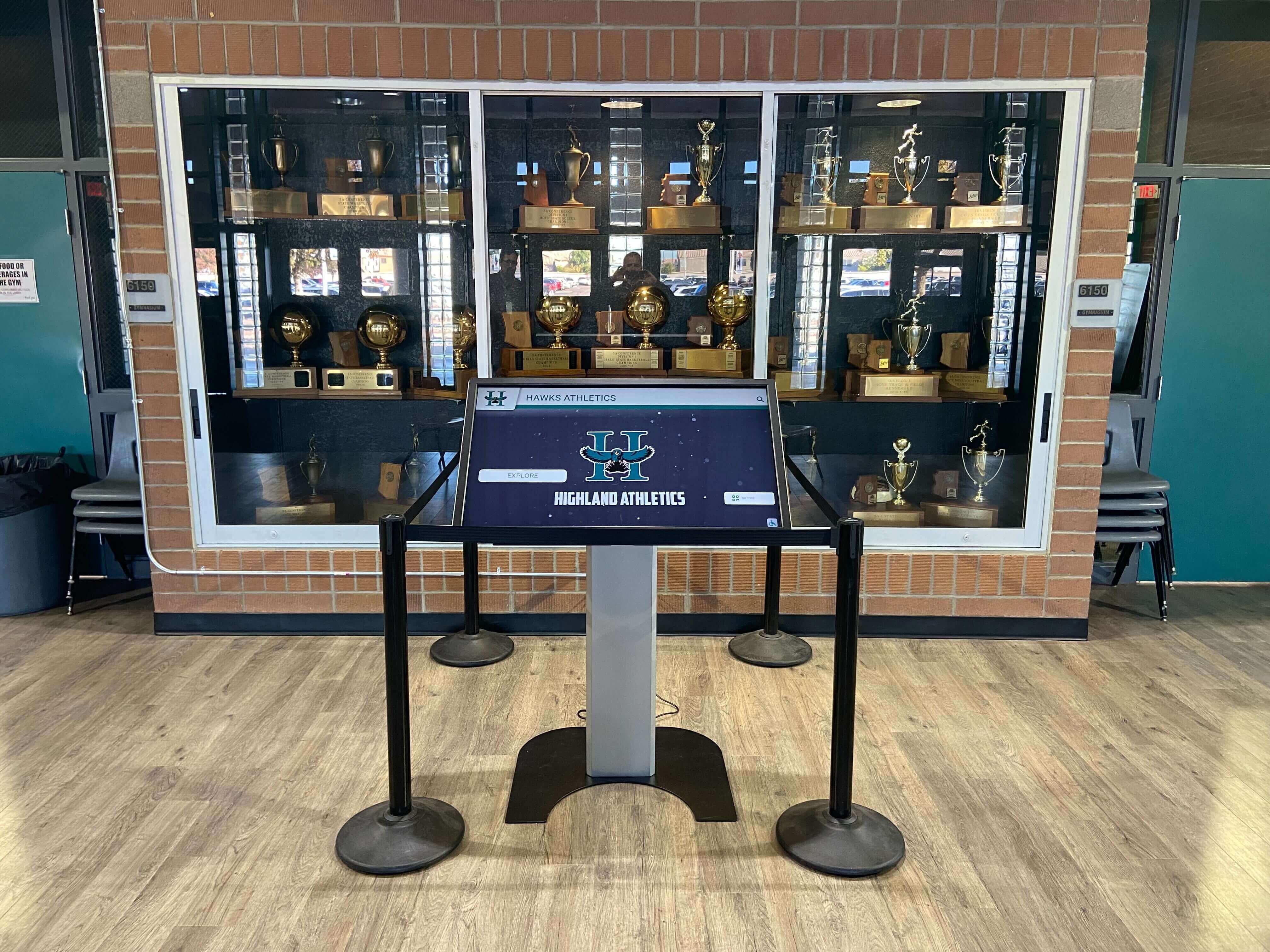
Trophy case corridors that integrate digital kiosks alongside physical cases share LED lighting infrastructure — driver ripple affecting physical case fixture quality also affects the visual context for digital recognition elements in the same space
What a Qualified Installer Does With Ripple Measurement Results
When facilities team documentation shows that one or more drivers in a trophy case corridor fall into the Escalate column of the decision table, the next step is engaging a licensed electrician or qualified lighting technician for corrective assessment. The measurement record created in Step 7 of the procedure tells the electrician what is known; their role is to determine what to do about it.
Typical corrective paths include:
Driver replacement with specified ripple rating. For a driver that has aged beyond acceptable ripple performance, the corrective action is replacement with a unit carrying a documented ripple specification. The specification should be stated in the purchase order: “Output ripple below 5% at full output and at the lowest operating dim level used in this installation.” Verbal agreements are not adequate; a written specification is what survives procurement staff turnover and protects the school if a delivered driver does not meet the requirement.
Dimming control adjustment. For cases where elevated ripple appears only at specific dim levels, a qualified controls technician may be able to adjust the dimming range or protocol to avoid the operating point where the driver produces excessive ripple. This is a configuration adjustment rather than a hardware replacement, but it requires documented control system access and should not be performed without a record of the change.
Fixture thermal environment improvement. For trophy cases where elevated driver operating temperature is documented as the accelerating factor in ripple increase, the corrective action may involve improving case ventilation or relocating drivers to a cooler mounting position within the fixture enclosure. This typically requires a licensed electrician to modify fixture wiring and should be treated as a facilities project rather than a routine maintenance task.
Schools weighing whether recurring driver ripple issues warrant a broader recognition technology evaluation will find context in comparisons between physical trophy case maintenance requirements and digital recognition alternatives. The difference in ongoing maintenance burden between physical LED fixture management and cloud-managed digital displays is a factor in that evaluation — explored in resources such as the digital hall of fame display vs. traditional trophy case comparison at Touch Hall of Fame and the digital hall of fame vs. traditional trophy case analysis at Hall of Fame Online. The comparison is not either/or — many schools maintain physical cases for championship hardware while adding digital recognition for current-season content and alumni archives — but understanding the maintenance commitments on both sides informs a more accurate budget conversation.
Frequently Asked Questions
What is LED driver output ripple in the context of trophy case lighting? LED driver output ripple is the residual AC voltage variation that remains on the driver’s DC output after conversion from mains AC power. No LED driver converts AC to DC with perfect smoothness; the rectifier and filter circuit always leaves a small cyclic fluctuation at the mains harmonic frequency (120 Hz in North America, 100 Hz in 50 Hz regions). This ripple, when sufficiently large, causes the current delivered to the LED module to vary at the same frequency — modulating light output and producing the conditions associated with flicker, camera banding, and photosensitive visitor discomfort.
How does LED driver ripple differ from the Flicker Index measurement? Ripple is an electrical measurement taken at the driver’s DC output terminals, quantifying the AC component remaining in the output voltage or current. Flicker Index is a photometric measurement taken at the fixture’s light output, quantifying the cyclic variation in actual lumen output. High driver ripple causes high Flicker Index: the electrical instability of the driver produces the photometric instability of the fixture. Ripple measurement is the diagnostic upstream of the flicker symptom — useful for confirming the cause and for selecting replacement drivers with documented ripple specifications.
Can a school facilities team take ripple measurements safely? Facilities staff can safely perform the 240 fps video screening test and document environmental conditions and driver inventory without any contact with electrical terminals. Actual electrical measurement of driver output ripple — using a multimeter or oscilloscope at the driver’s DC output terminals — requires a qualified electrician or lighting technician to handle fixture access, because trophy case fixtures contain line-voltage wiring in the same enclosures as the driver DC output. The facilities team’s role in the measurement procedure is documentation, observation, and escalation; the electrical measurements are performed by licensed professionals.
What ripple percentage is acceptable for school trophy case LED drivers? A commonly applied threshold for display-quality LED lighting is output ripple below 5% of the DC output voltage, measured at all normal operating dim levels. Drivers meeting DLC Premium qualification have been independently tested to produce Flicker Index below 0.04 at 100–120 Hz, which corresponds to light output modulation depths consistent with low-ripple driver designs. Budget drivers without published ripple specifications or DLC Premium listing may produce ripple well above this threshold, particularly as they age and capacitor performance declines.
Why does ripple get worse over time in the same driver? The output filter capacitors in an LED driver — typically electrolytic aluminum capacitors — lose capacitance as they accumulate thermal cycling and operating hours. Reduced capacitance means less effective filtering of the rectifier output, which allows more AC ripple to pass through to the DC output. The rate of capacitor aging accelerates with elevated operating temperature: a driver running 20°C above its rated ambient loses capacitance significantly faster than a driver at rated ambient conditions. Trophy case fixtures in enclosed wood or metal structures with limited airflow are particularly prone to this thermal acceleration.
What should a measurement record include before being forwarded to an electrician? A complete ripple measurement record should include: driver model and installation date, fixture position identifier on a corridor map, 240 fps video screening result, DC output voltage at the time of measurement, AC ripple voltage in millivolts RMS, calculated ripple percentage, dim level and ambient temperature at the time of measurement, oscilloscope waveform description if captured, name and license number of the qualified technician who performed electrical measurements, and the date. This record is the basis for any replacement decision, procurement specification for a replacement driver, and the baseline for future comparison measurements.
Does whole-building electrical quality affect driver ripple? Yes, but indirectly. Building electrical quality — power factor, harmonic distortion from other loads, and supply voltage variation — affects how the driver’s rectifier stage operates, which in turn affects how much AC content the output filter must remove. A driver designed for low ripple in a clean electrical environment may produce higher ripple on a supply with significant harmonic content from large motor loads or variable frequency drives on the same distribution panel. Measuring ripple under actual building operating conditions — with the HVAC running, lights on across the building, and motors cycling — captures the real ripple that trophy case fixtures experience, not a best-case laboratory result.
When should schools consider digital recognition displays instead of continuing to maintain LED driver infrastructure? When ripple measurement audits reveal that trophy case LED drivers are aging faster than anticipated, or when driver replacement cycles are consuming facilities resources on a frequency that disrupts other maintenance priorities, schools often evaluate whether the recognition program goals are better served by adding a digital display component. Digital recognition platforms manage current-season achievements, alumni archives, and interactive content independently of physical case lighting infrastructure. The physical cases and their LED drivers remain for championship hardware; the digital display handles the content that would otherwise require ongoing lighting infrastructure maintenance to remain visible. The comparison of maintenance requirements and recognition capacity between physical and digital approaches is covered in the digital hall of fame display comparison at Touch Wall.
LED driver output ripple is the electrical condition that sits upstream of every visible light quality symptom in a school trophy case corridor — the rolling bands in the yearbook photographer’s footage, the headache complaint from the parent who spent three hours at the athletic banquet, the coaching staff’s observation that the championship corridor “just doesn’t look right” without anyone being able to say exactly why. It is measurable before symptoms appear severe enough to generate complaints, documentable with equipment available to most school facilities teams, and correctable by a qualified electrician working from a clear measurement record.
The seven-step procedure in this guide produces that measurement record: a documented baseline of driver electrical performance, taken under real operating conditions, that tells a qualified installer exactly what the driver is doing and what corrective action the data supports. Schools that build driver ripple documentation into their annual trophy case facilities audit — alongside visual inspections, SPD status checks, and thermal environment assessments — protect the recognition infrastructure that championship hardware and decades of school achievement depend on for their visibility.
See What Your Recognition Program Looks Like With Digital Displays
If your facilities team is managing aging LED driver infrastructure in trophy case corridors, Rocket Alumni Solutions can show you how schools are building recognition programs that extend beyond what physical case lighting can reliably support. Cloud-managed digital trophy cases and hall of fame displays with interactive touchscreens, remote content management, unlimited recognition capacity, and factory-calibrated display hardware — no driver ripple audits, no capacitor degradation timelines, and no dark corridor during senior night because a filter component failed silently. See the platform in a live demo configured for your school's recognition goals.
Schedule Your DemoLive Example: Rocket Alumni Solutions Touchscreen Display
Interact with a live example (16:9 scaled 1920x1080 display). All content is automatically responsive to all screen sizes and orientations.