The Easiest Touchscreen Solution



Live Example: Rocket Alumni Solutions Touchscreen Display
Interact with a live example (16:9 scaled 1920x1080 display). All content is automatically responsive to all screen sizes and orientations.
Intent: research — trophy case constant-current LED driver replacement requires matching the replacement driver’s output current rating in milliamps to the LED load’s specification, confirming that the driver’s output voltage range encompasses the LED string’s forward voltage, verifying compatibility with whatever dimming protocol the trophy case control system uses, and ensuring that installation is completed by a qualified electrician meeting state licensing and NEC requirements. Because schools replace individual failed drivers rather than full fixture systems, procurement errors — wrong current rating, incompatible dimming method, or under-certified hardware — are common and produce outcomes that range from reduced display brightness to premature LED failure. This checklist addresses each verification step before any replacement driver is ordered.
When a constant-current LED driver in a school trophy case fails, the immediate symptom is obvious: one zone of the display goes dark, dims significantly, or begins to flicker in a way that cannot be corrected by adjusting a dimmer. What is less obvious is that ordering a physically similar replacement driver without verifying five specific parameters before purchase reliably produces a second failure — either because the replacement drives the LED string at the wrong current, because it cannot communicate with the building’s existing dimmer, or because it ships from a supplier who does not hold the certifications required for code-compliant installation in a school facility.
A preflight checklist — completed before the purchase order is generated — costs less than fifteen minutes and prevents the service callbacks, re-procurement cycles, and LED damage that incorrect driver replacements produce.

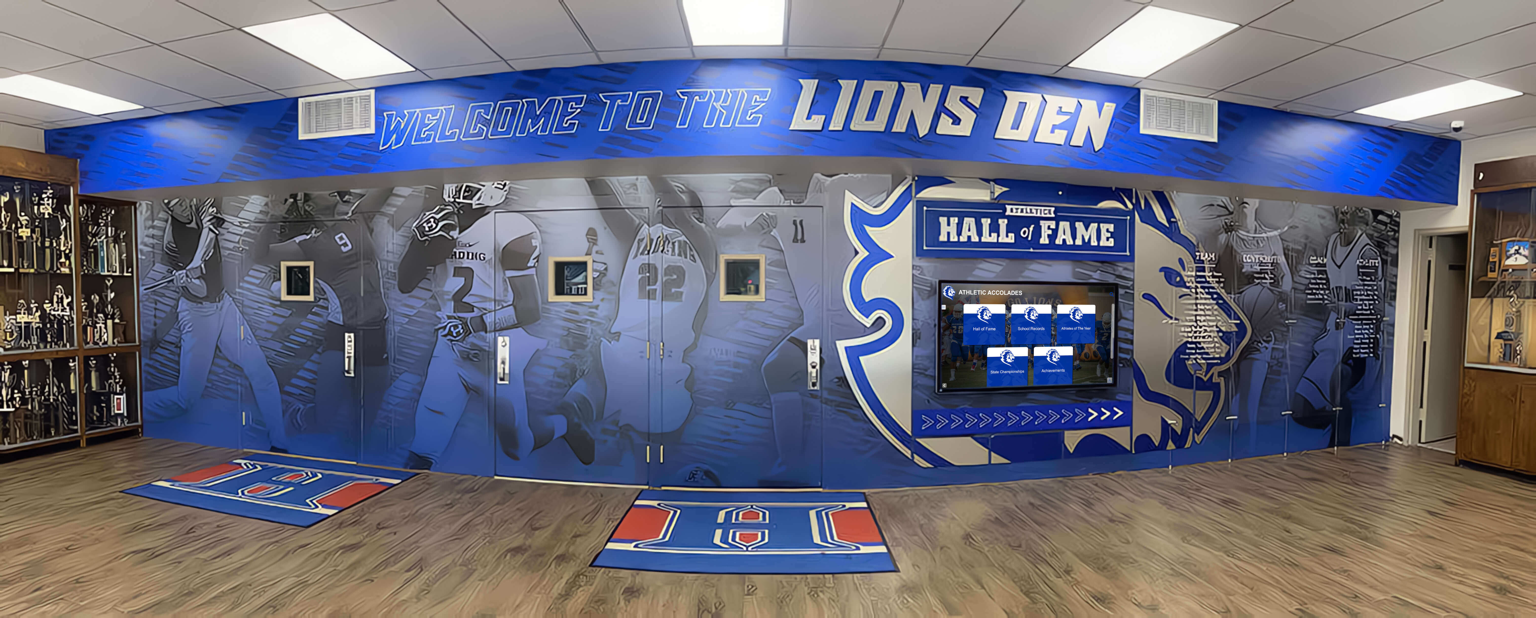
Trophy case corridors that combine murals, physical cases, and recognition displays depend on consistent driver operation across every zone — a failed driver in any position disrupts the display's visual continuity for visitors, families, and school leadership
What Constant-Current Drivers Do and Why Matching Matters
An LED driver is the power supply that converts the AC line voltage entering the fixture into the DC output the LED module requires. A constant-current driver — as opposed to a constant-voltage driver — maintains a fixed output current in milliamps regardless of the load’s forward voltage. The output voltage varies automatically to hold that current steady.
This design protects the LED module from the thermal runaway failure mode that kills LEDs driven by unregulated power: as LED junction temperature rises, forward voltage drops slightly, which in an unregulated circuit causes current to increase, which raises temperature further in a feedback loop that ends in device failure. The constant-current driver interrupts this loop by monitoring and adjusting output voltage to keep current at the rated value regardless of what the LED’s temperature is doing.
The consequence for replacement procurement is specific: replacing a failed constant-current driver with a unit of identical wattage but different current rating will either overdrive the LED string — shortening its life measurably — or underdrive it, producing a display that is permanently dimmer than its neighbors without any clear indication of why. Neither outcome is detectable by visual inspection during commissioning. Both are detectable only by reading the failed driver’s label before discarding it.
Common Output Current Ratings
Constant-current LED drivers for fixture applications are manufactured at standardized current levels: 350 mA, 500 mA, 700 mA, 1050 mA, and 1400 mA are the most common values for commercial display and downlight fixtures. Some specialty trophy case fixtures use non-standard values — 525 mA or 900 mA appear in certain manufacturer product lines. The rated current is always printed on the driver label, typically alongside the output voltage range and wattage. Photograph or transcribe both the current rating and the output voltage range before removing the failed driver from the fixture.
Why Wattage Is Not a Sufficient Specification
A 20W driver can be manufactured with an output current of 350 mA at a higher output voltage, or 700 mA at a lower output voltage. Both configurations deliver 20W to the load but drive the LED string at very different current levels. Ordering a replacement by wattage alone without specifying current rating will produce a match approximately half the time and a mismatch the other half — with no reliable way to distinguish the outcome until the fixture has run for enough hours to produce measurably different lumen output or early LED degradation. Current rating in milliamps is the non-negotiable specification for a constant-current driver replacement.
The Preflight Checklist: Six Parameters to Verify Before Ordering
Complete this checklist before generating a purchase order for any replacement constant-current LED driver. Each item takes less than two minutes to verify from the failed driver’s label and the existing control system documentation.
| Preflight Item | Where to Find It | What to Record | Consequence of Mismatch |
|---|---|---|---|
| 1. Output current rating (mA) | Failed driver label; original fixture specification sheet | Current value in milliamps (e.g., 700 mA) | LED overdrive shortens life; underdrive produces permanent dim zone |
| 2. Output voltage range (V) | Failed driver label (listed as a range, e.g., 18–42V) | Minimum and maximum output voltage | Driver cannot regulate current if LED string Vf falls outside driver's range |
| 3. Dimming protocol | Failed driver label; control system documentation; dimmer panel labeling | 0–10V, DALI, PWM, Triac, or non-dimming | Driver cannot respond to dimmer commands; may cause flicker, noise, or full-output lock |
| 4. Physical form factor and mounting | Physical measurement of failed driver; fixture enclosure drawings | Body dimensions (L × W × H); conduit knockouts; DIN-rail or surface mount | Replacement physically cannot fit in fixture enclosure or does not align with mounting points |
| 5. Certifications required | Original specifications; school procurement policy; local AHJ requirements | UL 8750 listing; DLC listing (if energy rebate is claimed); applicable ratings (damp, wet, enclosed) | Non-listed equipment fails inspection; DLC gap voids utility rebate application |
| 6. Installation qualification requirement | State electrical licensing board; school district procurement policy; NEC Article 110 | Licensed electrician required; specific license class if applicable | Unlicensed installation fails inspection; school liability for code violation in occupied facility |
Item 1: Matching the Output Current Rating
The output current rating on a constant-current driver is the parameter that must match exactly — not approximately, not within 10%, but exactly within the range the LED module manufacturer specifies for that product. LED modules are rated for a maximum forward current, typically at 350 mA, 700 mA, or 1050 mA. Some modules accept a range — a module rated “350–700 mA” can run at either value — but that range is documented in the module specification sheet, not determinable from visual inspection.
Finding the current rating on the failed driver: The output label section will read something like “OUTPUT: 18–42V DC, 700 mA, 15–29W” or “Iout: 350 mA.” Photograph the entire driver label before removing the unit from the enclosure. If the label is damaged or unreadable, locate the original fixture’s submittals or cut sheet — the driver model number stamped on the housing can be cross-referenced against the manufacturer’s specification database to confirm the current rating.
If the failed driver model is discontinued: Contact the original fixture manufacturer’s technical support line with the fixture model number and driver model number. Most manufacturers maintain cross-reference guides listing approved replacement driver models with compatible current and voltage specifications. Using the manufacturer’s approved replacement list is more reliable than independently sourcing a driver with matching printed specifications — manufacturer-approved replacements have been thermal-compatibility tested within the specific fixture enclosure, which commodity replacements have not.
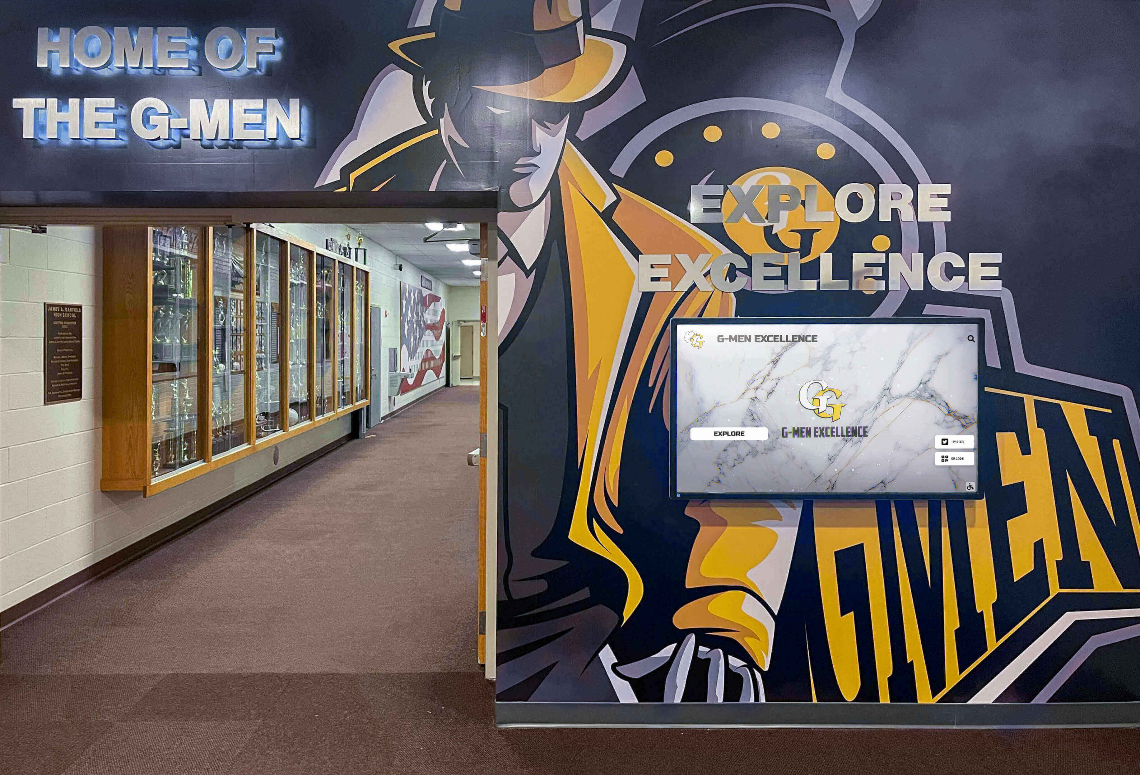
Trophy case corridors that combine physical and digital recognition elements depend on matched driver specifications across all fixture zones — a mismatched replacement driver in a single zone creates visible brightness inconsistency that is disproportionately noticeable in a symmetrical corridor installation
Item 2: Verifying the Output Voltage Range
A constant-current driver’s output voltage range defines the span of forward voltages it can accommodate while holding current constant. A driver rated “OUTPUT: 20–50V DC, 700 mA” will regulate current accurately for any LED load with a combined forward voltage between 20 and 50 volts at 700 mA. If the LED string’s forward voltage at operating temperature falls outside that window — because the replacement driver has a narrower range than the original, or because a different LED module has been substituted in the fixture — the driver’s regulation loop loses authority and current delivery becomes unreliable.
Forward voltage of an LED string equals the sum of individual LED forward voltages in the series chain. A string of ten LEDs each rated at 3.4V forward voltage at 700 mA produces a string forward voltage of approximately 34V. A replacement driver with an output range of 36–54V cannot regulate this load; the string forward voltage falls below the driver’s minimum, and the driver will either deliver reduced current, shut down on its protection threshold, or oscillate.
What to record: Note the failed driver’s output voltage range (both minimum and maximum values) from the label. Confirm that the replacement driver’s specified output voltage range encompasses the LED string’s operating forward voltage, with margin. A replacement rated 18–42V is adequate for a 34V string; a replacement rated 36–54V is not. When in doubt, cross-reference the LED module specification sheet for forward voltage at the rated current before finalizing the driver selection.
Item 3: Dimming Protocol Compatibility
Dimming protocol is the parameter most frequently overlooked in trophy case driver replacement procurement, and it produces the most disruptive post-installation failures. A driver installed with a mismatched dimming interface may operate at full output and ignore all dimmer commands, flicker at mid-range settings, generate audible noise from the fixture, or shut down entirely when the building automation system sends a command the driver cannot interpret.
| Dimming Protocol | How to Identify It | Key Compatibility Check | Common Trophy Case Context |
|---|---|---|---|
| 0–10V | Two additional low-voltage wires (typically purple and gray) from driver to dimmer; driver label notes "0–10V" or "1–10V" | Confirm dimmer is rated 0–10V DC (not 1–10V if driver requires 0V to reach minimum); check polarity requirements on driver datasheet | Standard in older athletic corridor installations and basic renovation projects; compatible dimmers are widely available |
| DALI | Two-wire DALI bus connection labeled "DALI+" and "DALI−" or "DA" on driver; controller software shows device on bus | Replacement must be IEC 62386 certified (DALI Type 6 for LED gear); confirm bus address re-assignment after replacement | Installed in schools with building automation integration or multi-zone scene control; prior DALI commissioning documentation required for re-addressing |
| PWM | Single additional signal wire for PWM input; driver label notes "PWM dimming" with operating frequency range | Match PWM frequency range (typically 100–3000 Hz) and signal voltage (3.3V, 5V, or 10V logic) | Less common in school installations; more frequent in retrofit LED strip or display accent applications |
| Triac / Phase-cut | No additional control wires; driver connects directly to the switched hot from a wall dimmer; label notes "TRIAC," "leading-edge," or "trailing-edge" | Confirm whether dimmer is leading-edge (TRIAC) or trailing-edge (ELV/MLV); not all drivers support both; check minimum load rating on dimmer | Found in older installations where original fluorescent dimmers were left in place; incompatibility between driver type and dimmer type is a frequent flicker cause in retrofit situations |
| Non-dimming | No additional control wires; driver operates at fixed output; label has no dimming notation | Verify the fixture circuit is switched-only; confirm no dimmer is installed in the circuit that would interfere with driver output | Appropriate for trophy case positions on simple switched circuits without adjustment requirements |
DALI installations require additional steps. A replacement driver for a DALI-controlled trophy case does not arrive with a pre-assigned DALI address. After installation, the new driver must be addressed using the DALI controller’s commissioning software, assigned to the same group as the driver it replaced, and verified against the existing scene programming. Schools that lost their DALI commissioning documentation during staff transitions may need a qualified controls technician to re-identify group assignments before the replacement is fully operational. For schools managing existing DALI systems, the thermal management requirements documented in resources like school trophy case LED heat assessment guides are relevant to the driver replacement decision because elevated junction temperatures from inadequate heat dissipation accelerate driver failure rates — replacing a failed driver without addressing the thermal environment that caused the failure produces a repeat failure on a shorter timeline.
Managing Recognition Displays Alongside Driver Maintenance?
Schools cycling through trophy case driver replacements often find that digital recognition platforms reduce long-term maintenance burden while expanding what the recognition program can display. Rocket Alumni Solutions works with athletic directors and facilities teams to evaluate cloud-managed display options that match school recognition goals.
Request a ConsultationItem 4: Physical Form Factor and Mounting
Constant-current LED drivers intended for fixture applications are manufactured in several physical formats: rectangular panel-mount enclosures, cylindrical inline formats, and DIN-rail-mount housings. Replacing a panel-mount driver with a DIN-rail driver — even with identical electrical specifications — requires modifying the fixture enclosure or sourcing a separate DIN-rail carrier, which adds cost and labor that was not in the original replacement estimate.
Measurements to record from the failed driver:
- Overall body dimensions: length × width × height in millimeters or inches
- Input and output wire gauge and lead length (replacement must accommodate same wire sizes)
- Mounting hole pattern or DIN-rail clip type
- Conduit knockout locations if the driver is in a dedicated enclosure
Most fixture manufacturers specify replacement driver part numbers in the fixture’s installation documentation or on the manufacturer’s product page under “accessories” or “spare parts.” Where this information is available, use it — physically confirmed replacement part numbers eliminate form-factor uncertainty at no additional research cost.
Item 5: Certifications and Code Requirements
UL listing. NEC Section 110.2 requires that electrical equipment installed in a wiring system be listed and labeled by a nationally recognized testing laboratory (NRTL) unless the authority having jurisdiction (AHJ) specifically approves unlisted equipment for a particular application. In practice, this means replacement LED drivers installed in school facilities must carry UL listing or equivalent NRTL certification. UL 8750 is the applicable standard for LED drivers and power supplies used in lighting products. Confirm the replacement driver’s listing mark before purchase; budget-channel suppliers occasionally ship units without valid NRTL certification, which creates inspection and insurance compliance exposure for the school.
DLC listing for energy incentive claims. If your school district submits energy efficiency rebate applications to the local utility for lighting equipment, the DesignLights Consortium (DLC) qualification status of replacement components is a procurement requirement, not a preference. DLC maintains a qualified products list; drivers and luminaires on the list are eligible for standard or premium tier rebates depending on their efficiency ratings. A non-DLC replacement driver installed in an otherwise DLC-qualified fixture can void the rebate eligibility for that fixture in the reporting period. Check the DLC qualified products database before procurement if rebate claims are planned.
Wet or damp location rating. Trophy cases in entrance lobbies, covered outdoor display areas, or humid athletic corridors may require drivers rated for damp or wet locations under NEC Article 410. A driver rated for dry locations only — the default for most commercial LED drivers — is not code-compliant in a damp-rated fixture enclosure. Confirm the failed driver’s location rating from its label and match it in the replacement.
Item 6: Qualified Installation Requirements
Driver replacement involves disconnecting and reconnecting line-voltage wiring inside a fixture or driver enclosure. In the United States, this work falls under NEC requirements for licensed electrical work. State electrical licensing requirements determine which license class is required for this task in a school facility:
- Most states require a licensed journeyman or master electrician for fixture-level wiring work in an occupied commercial building, including schools.
- Some states have maintenance electrician exemptions for work performed by school district employees under the supervision of a licensed electrician — but the exemption conditions vary significantly by state and are not universally applicable to driver replacement.
- Schools in states without clear maintenance exemptions should not assign driver replacement to custodial staff without first confirming with the state licensing board that the task falls within an applicable exemption.
Practical approach for school facilities teams: If the trophy case driver replacement is part of a broader electrical maintenance contract, confirm with the contractor that the technician completing the work holds the applicable state license before the visit. If procurement through a local electrical distributor includes installation, request confirmation of license class and insurance coverage in writing before the scheduled service date.
The same principle applies to the inspection requirement: driver replacements that require opening a fixture or enclosure may require an electrical inspection by the local AHJ depending on jurisdiction and permit threshold. Small replacement tasks in many jurisdictions do not require permits, but the threshold varies. When in doubt, check with the district’s facilities director or the local AHJ directly rather than assuming no permit is needed.
For schools planning broader trophy case renovations that address both driver infrastructure and display design, resources on school trophy case design from traditional to digital can help frame the decision between maintaining existing fixture infrastructure and evaluating a more comprehensive recognition display upgrade.
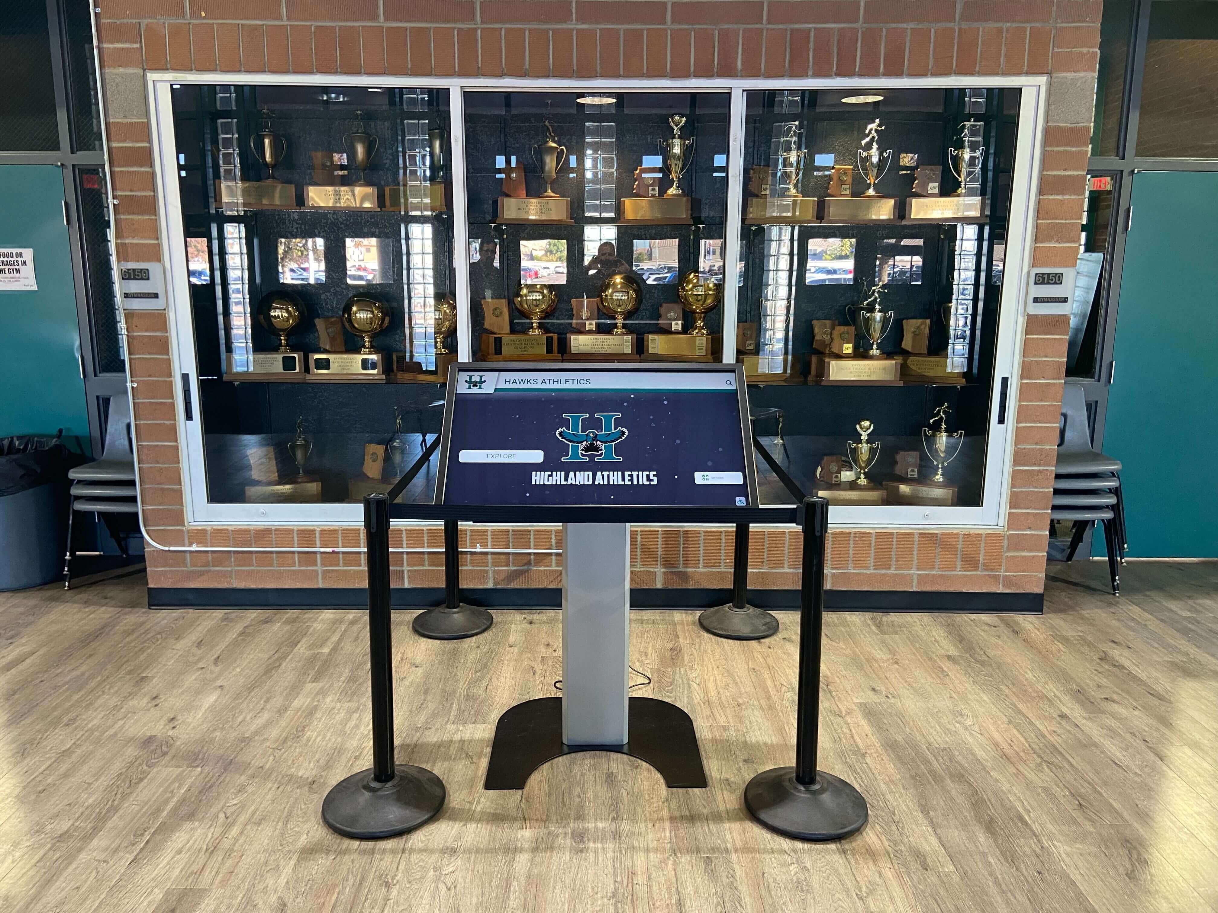
Schools integrating digital recognition displays alongside traditional trophy cases manage two distinct sets of electrical and maintenance specifications — consistent procurement and installation practices across both systems reduce long-term service burden
Documenting the Replacement
A driver replacement without documentation repeats the same procurement guesswork the next time a failure occurs in the same zone. Record the following before closing the fixture:
| Documentation Item | Where to Store It |
|---|---|
| Replacement driver manufacturer, model number, and date of installation | Facilities maintenance log; fixture label inside enclosure; laminated card on the driver enclosure panel |
| Output current rating (mA) and output voltage range | Same locations as above |
| Dimming protocol and any re-commissioning steps completed (DALI address, group assignment) | Facilities log; DALI controller configuration backup file if applicable |
| Certifications confirmed (UL listing number, DLC qualification status) | Facilities log; procurement file for rebate documentation |
| Installing contractor name and license number | Facilities log; school district vendor file |
| Failed driver model (photographed label or transcribed specifications) | Facilities log — retained as the specification reference for the next replacement cycle |
Schools developing comprehensive recognition programs that extend beyond individual driver maintenance — including senior class awards displays and programmatic recognition content — benefit from treating driver documentation as part of a broader facilities record rather than a one-off repair note. The documentation created at each driver replacement event becomes the institutional knowledge that prevents repeat procurement errors across staff transitions.
Frequently Asked Questions
Conclusion: Preflight Before Purchase Prevents Repeat Service Calls
A constant-current LED driver replacement in a school trophy case that goes correctly is an unremarkable fifteen-minute service event. One that goes wrong — because the current rating does not match, because the dimming protocol is incompatible, or because a non-listed driver fails inspection — produces a multi-week procurement and rework cycle that costs several times the original service call.
The preflight checklist costs nothing but time: photograph the failed driver’s label before removing it, confirm the output current rating in milliamps, check that the replacement’s output voltage range encompasses the LED string’s forward voltage, match the dimming protocol to the existing control system, confirm UL listing and any applicable DLC qualification, and verify that installation is assigned to a contractor holding the required state electrical license. Document all six parameters in the maintenance log before the replacement driver ships.
Schools that treat driver replacement documentation as a routine facilities record — rather than a one-off repair note — build the institutional continuity that prevents the same procurement guesswork from recurring at the next failure event, regardless of which staff member is managing facilities at that time.
See How Schools Manage Recognition Content Without the Driver Maintenance Cycle
Rocket Alumni Solutions works with athletic directors, administrators, and facilities teams to evaluate cloud-managed digital recognition platforms that complement physical trophy case investments — with unlimited content capacity, remote updates, and factory-calibrated display hardware that eliminates the driver replacement and lighting maintenance cycle for the recognition display itself. See the platform in a live demo configured for your school's recognition program.
Schedule Your DemoLive Example: Rocket Alumni Solutions Touchscreen Display
Interact with a live example (16:9 scaled 1920x1080 display). All content is automatically responsive to all screen sizes and orientations.