


Reviewing power factor on LED driver specification sheets before a school trophy case lighting upgrade is a practical step that helps facilities teams understand how much current each driver will draw from the branch circuit — not just how many watts it will consume. LED drivers with lower power factor draw more apparent current than their wattage alone implies, which affects circuit sizing, breaker loading, and dimmer compatibility in ways that a simple wattage count does not reveal. This guide explains what power factor is, how to locate and interpret the relevant ratings in supplier documentation, and what questions a qualified electrician should review before fixtures are installed in the school’s athletic trophy case corridor.
When an athletic director approves a trophy case LED lighting upgrade, the facilities team usually focuses on wattage and lumens: how much light, and how much energy will it use. Both matter. But the specification sheets for LED drivers contain a third input parameter — power factor — that determines how much current the driver actually draws from the circuit, independent of how efficiently it converts that current to light. In a corridor where a championship trophy wall, a retired-jersey display, and a hall-of-fame section all share branch circuit capacity with digital recognition panels and other loads, understanding input current from the driver spec sheet is part of planning a reliable installation, not an afterthought for the electrician.
This guide walks school facilities staff and athletic directors through what power factor means in the context of LED driver specifications, how it differs from efficiency, inrush current, and output ripple, and how to use the information in supplier documentation to ask better questions before installation begins.

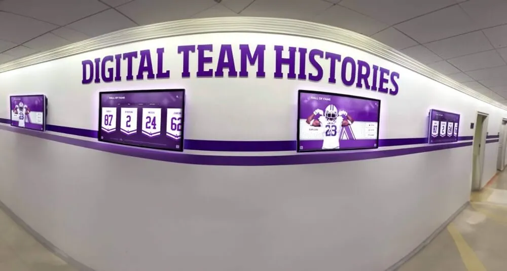
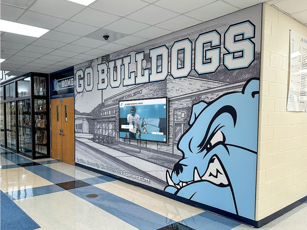
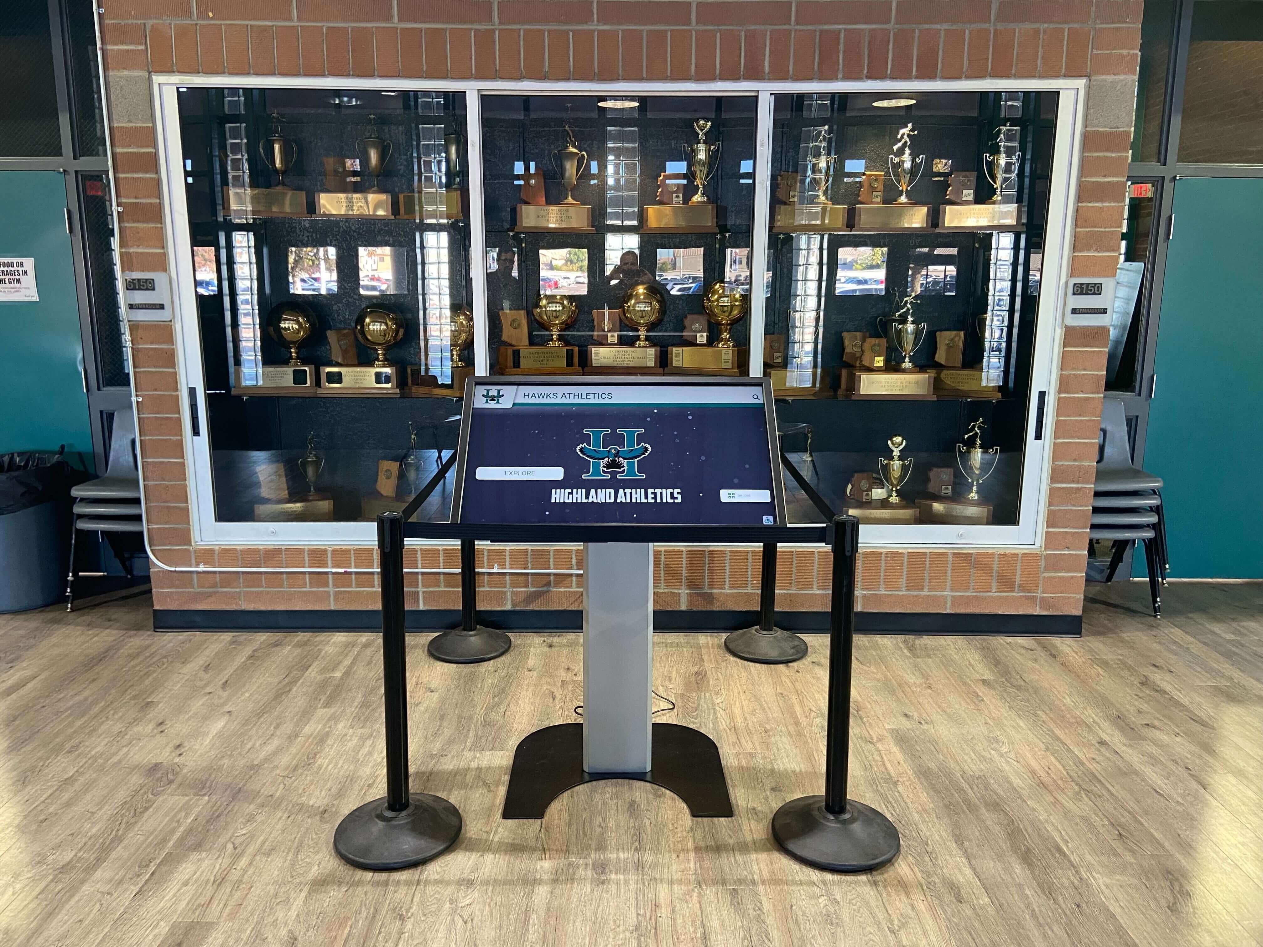
Trophy case corridors that combine physical cases with digital recognition panels share branch circuit capacity — LED driver input ratings inform circuit planning across the full corridor load, not just the fixture wattage
What Power Factor Is and Why It Appears on Driver Spec Sheets
Power factor is the ratio of real power — the watts that do actual work — to apparent power, which is the total electrical demand the driver places on the circuit in volt-amperes (VA). A driver rated at 24 real watts with a power factor of 0.60 draws 40 apparent VA from the circuit (24 ÷ 0.60 = 40). A driver rated at 24 real watts with a power factor of 0.95 draws approximately 25.3 VA. Both drivers consume 24 watts; the low-PF driver places significantly more demand on the circuit to deliver them.
Power factor ranges from 0.0 to 1.0 (or 0% to 100%). A driver with PF = 1.0 draws only what it uses; all the current from the circuit is converted directly into useful output. A driver with PF = 0.5 draws twice as much apparent current as a unity-PF driver of the same wattage. In practice, LED drivers fall into broad categories:
- Commodity or non-corrected drivers: PF commonly in the lower range. No active power factor correction circuitry; the driver draws current in sharp pulses that lag or lead the supply voltage.
- High-PF drivers with active PFC: Contain a power factor correction (PFC) stage that draws current more continuously across the AC cycle, reducing reactive demand. Supplier documentation for these models specifies the PF achieved.
- DLC-qualified and ENERGY STAR-certified drivers: Both programs establish minimum power factor thresholds for listed products; qualifying drivers for most commercial categories have been independently tested to meet published PF requirements. The DOE FEMP guidance on purchasing energy-efficient commercial and industrial LED luminaires provides the federal institutional perspective on input power specifications when evaluating LED products for school and government facility purchases.
Power factor appears as a decimal (0.95) or percentage (95%) on driver specification sheets. Both express the same value. Verify the current specification for any specific product before purchase, as driver models and their ratings change.
Power Factor Is Not Efficiency, Inrush Current, or Output Ripple
Four distinct driver characteristics appear in LED specification sheets and pre-installation planning discussions: power factor, efficiency, inrush current, and output ripple. They address different aspects of driver behavior, measured at different points in the circuit, and require separate evaluation. Conflating them leads to decisions that address the wrong parameter.
| Characteristic | What It Measures | Where It Applies | Relevant for Trophy Case Planning |
|---|---|---|---|
| Power Factor (PF) | Ratio of real input power (W) to apparent input power (VA); how effectively the driver uses the current it draws from the AC supply | AC input side of the driver — the branch circuit and building electrical system | Circuit sizing, breaker loading, dimmer compatibility, and utility demand considerations for larger corridor installations |
| Efficiency | Ratio of useful output power (W delivered to the LED string) to total real input power (W consumed); also expressed as luminaire efficacy in lumens per watt | Internal driver conversion — from AC input to DC output; reflects how much input power becomes light versus heat | Operating cost and heat generation; an efficient driver wastes less input power as heat inside the enclosed trophy case fixture |
| Inrush Current | Peak current drawn at the moment of power-on, as input capacitors charge from zero; typically expressed in amperes and milliseconds duration | AC input side — circuit breaker, switch, dimmer, relay, and wiring experience the inrush pulse at startup | Breaker sizing for simultaneous startup of multiple fixtures; dimmer and relay compatibility at power-on |
| Output Ripple | Residual AC variation in the driver's DC output current or voltage after conversion; typically expressed as percentage of DC output or millivolts RMS | DC output side of the driver — determines light output modulation at the LED fixture | Photographic and video quality in the recognition corridor; photosensitive visitor comfort during recognition events |
A driver with high power factor can still be inefficient, can still produce high inrush current at startup, and can still have high output ripple at the DC output. These characteristics are evaluated separately from supplier documentation. Except for efficiency — which involves only internal driver parameters — each requires its own review before an installation decision is made. A thorough pre-upgrade review addresses all four; a power-factor review is one component of that set, not a substitute for the others.
Reading Input Ratings on LED Driver Specification Sheets
A commercial LED driver specification sheet contains several input-side parameters. Knowing which values to locate — and what to calculate when a value is missing — is the practical task this review addresses.
Parameters to locate on the driver spec sheet:
- Input voltage range: The AC supply voltages the driver is rated for. Confirm your building supply voltage falls within this range before comparing any other parameter.
- Input current (A): The AC current the driver draws from the branch circuit at full output, at nominal supply voltage. This is the value used for circuit sizing calculations. Some sheets express this at a specific voltage; others express it across the input range.
- Input power (W): Real power consumed by the driver at full output. This is used for energy cost calculations and steady-state breaker load calculations.
- Apparent power (VA): Total volt-ampere demand on the circuit. If not listed explicitly, calculate it: VA = Input current (A) × Supply voltage (V). Alternatively, if power factor is listed: VA = Input power (W) ÷ Power Factor.
- Power factor (PF): Listed as a decimal or percentage. If not listed but input current and input power are available, calculate: PF = Input power (W) ÷ (Input current (A) × Supply voltage (V)).
- Total harmonic distortion (THD): The percentage of the input current that consists of harmonic frequencies rather than the fundamental AC frequency. High THD contributes to reactive load effects on the building’s electrical system. THD is closely related to PF in driver design but is reported separately; a driver with active PFC typically has lower THD as well. Check supplier documentation and ask your electrician whether local requirements specify a THD limit for institutional LED lighting.
Why input current is the most direct circuit planning value:
For circuit planning at the fixture level, input current at rated supply voltage is the most direct specification. A circuit breaker is sized for current, not watts. A dimmer is rated for current and load type. Knowing each LED driver in the trophy case corridor draws a documented current — and understanding why that figure may be higher than the wattage alone suggests, when PF is low — gives the electrician specific numbers to work with rather than estimates.

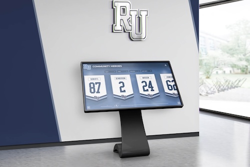
Recognition corridors with trophy displays, shield cases, and integrated digital screens share branch circuit capacity across multiple load types — LED driver input ratings inform how much of that capacity each fixture type consumes
Step-by-Step: Comparing Driver Input Ratings Before a Trophy Case Lighting Upgrade
The following steps are structured for facilities managers and athletic department staff working in coordination with a qualified electrician. Steps 1 through 4 are documentation and comparison tasks that facilities staff can complete from specification sheets. Steps 5 and 6 involve electrical assessment that a licensed electrician should review before installation proceeds.
Step 1 — Gather Specification Sheets for Every Driver Under Consideration
Before comparing input ratings, collect the data sheets for each LED driver or integrated fixture model you are evaluating. If a supplier cannot provide a specification sheet — or if the sheet does not include input current, input power, and power factor — request that documentation explicitly. Suppliers of commercial-grade drivers used in institutional applications provide this data as standard documentation. A driver whose input characteristics are not documented presents unknown electrical demands on the circuit; do not include it in the installation plan until documentation is obtained.
Document for each candidate driver:
- Manufacturer and model number
- Input voltage range
- Input current (A) at your building’s supply voltage
- Input power (W) at full output
- Power factor (PF) — listed or calculated
- Apparent power (VA) — listed or calculated
- THD, if listed
Step 2 — Calculate Apparent Power for Any Driver Where It Is Not Listed
If the specification sheet lists input current and supply voltage but not apparent power, calculate:
Apparent Power (VA) = Input Current (A) × Supply Voltage (V)
If the sheet lists input power and power factor but not input current, derive input current from apparent power:
Input Current (A) = [Input Power (W) ÷ Power Factor] ÷ Supply Voltage (V)
For example: a driver specification sheet lists input power of 30 W, power factor of 0.62, and supply voltage of 120 V.
- Apparent power = 30 ÷ 0.62 = 48.4 VA
- Input current = 48.4 ÷ 120 = 0.40 A
A different driver with the same 30 W input power but power factor of 0.95:
- Apparent power = 30 ÷ 0.95 = 31.6 VA
- Input current = 31.6 ÷ 120 = 0.26 A
Both provide the same 30 W of real power. The low-PF driver draws substantially more current from the branch circuit. The numbers above illustrate the calculation method using example values; always apply this formula to the actual figures in the specification sheets for the products you are evaluating.
Step 3 — Multiply Per-Fixture Input Current by the Number of Fixtures per Circuit
Count the total number of LED fixture positions connected to each branch circuit in the trophy case corridor. Multiply the per-fixture input current from the specification sheet by the number of fixtures to obtain the estimated total circuit draw at full load.
Compare this total to the circuit breaker’s rated amperage. For continuous loads — those operating more than three hours at a stretch, which trophy case corridor lighting during extended recognition events qualifies as — the NEC provides continuous-load sizing guidance that a licensed electrician can apply to your specific circuit and jurisdiction. A licensed electrician should confirm that the calculated total current is appropriate for the branch circuit, wiring gauge, and protection device installed.
The difference in input current between a lower-PF and higher-PF driver of the same wattage is small for any single fixture. Across many fixtures sharing a circuit that also serves digital display panels, AV equipment, or other connected loads, the difference accumulates. Provide your per-fixture input current figures and fixture count to the electrician rather than a wattage total — the electrician works in amperes, not watts, for circuit sizing.
Step 4 — Identify Whether Each Driver Carries a DLC or ENERGY STAR Qualification
Both DesignLights Consortium (DLC) qualification and ENERGY STAR certification for LED luminaires establish minimum power factor thresholds as part of their product requirements. A driver or luminaire that carries a current DLC listing or ENERGY STAR certification has been independently tested to confirm it meets the applicable PF floor for its product category. Check both programs’ online product databases using the specific manufacturer model number from the specification sheet.
The DOE FEMP guidance on purchasing energy-efficient commercial and industrial LED luminaires provides FEMP’s institutional framework for LED product selection, including input power specifications and the role of third-party qualification programs. FEMP purchasing guidance is updated periodically; verify the current version and the relevant product category before applying it to your purchase decision.
Qualification status does not replace reading the specification sheet. A product can carry a DLC or ENERGY STAR listing while still having input current and apparent power values that require review for your specific circuit configuration. Use certification status as a quality indicator that confirms independent testing has occurred — not as a substitute for the per-fixture calculations in Steps 2 and 3.
Step 5 — Compile a Comparison Summary and Forward to Your Electrician
Organize the results from Steps 1 through 4 into a comparison document that your licensed electrician can review before installation:
- One row per candidate driver model
- Input power (W)
- Power factor (PF) — listed or calculated
- Apparent power (VA) — listed or calculated
- Input current per fixture (A)
- Estimated total circuit current for the planned fixture count
- DLC and/or ENERGY STAR listing status
- Notes on any driver where documentation was incomplete or had to be calculated
This document becomes the basis for the electrician’s assessment of whether the existing circuit infrastructure is appropriate for each driver option. The electrician can add inrush current review (from the driver’s inrush specification) and dimmer or relay compatibility assessment to this framework — creating a complete pre-installation electrical record before the purchase decision is finalized.
Step 6 — Have a Qualified Electrician Assess Circuit Capacity and Compatibility
The input rating comparison in Steps 1 through 5 is a documentation task. Circuit capacity assessment, dimmer and relay compatibility review, and wiring adequacy determination require a licensed electrician. Provide the comparison summary to the electrician before the purchase decision is finalized and before any fixture installation begins.
The electrician’s review should confirm:
- Whether the total circuit current at full load, for each driver option, is within the circuit’s continuous-load capacity for the specific breaker and wiring configuration installed
- Whether the circuit’s dimmer (if installed) is compatible with the driver’s input type and rated load
- Whether the branch circuit wiring gauge is appropriate for the input current of the planned installation
- Whether the building’s electrical panel has adequate capacity for the circuit’s full connected load, including any other devices sharing the circuit
- Whether local jurisdiction requirements impose any additional considerations for institutional LED lighting input specifications
Recognize More Athletes Without the Electrical Planning Overhead
While your facilities team works through driver input rating comparisons for physical trophy cases, Rocket Alumni Solutions can show you how schools are extending their recognition programs with cloud-managed digital displays. Interactive touchscreens with factory-calibrated hardware, remote content management, unlimited recognition capacity, and WCAG 2.1 AA accessibility — no input current calculations, no PF comparisons, and no circuit sizing review for every recognition update. Explore the full recognition platform to see how digital displays complement what your facilities team maintains in the physical cases.
Book A DemoInput Rating Comparison Checklist: What to Locate in Supplier Documentation
The following table summarizes the key input specification parameters, where to find each in a driver specification sheet, and what each means for a school trophy case lighting upgrade. Use this as a checklist when evaluating documentation from multiple suppliers before bringing the comparison to your electrician.
| Specification Parameter | Where Found on Spec Sheet | What It Means for Your Installation | Action if Not Listed |
|---|---|---|---|
| Input power (W) | "Input power," "Power consumption," or "Wattage" — listed at full output, rated input voltage | Real energy consumed; determines operating cost and steady-state thermal load on driver components | Request from supplier; do not substitute LED string wattage, which excludes driver conversion losses |
| Power factor (PF) | "Power factor" or "PF" — listed as decimal (0.95) or percentage (95%) | Ratio of real to apparent power; determines how much apparent current the driver draws relative to its wattage | Calculate from input current and voltage if available: PF = W ÷ (A × V). Request from supplier if neither is available |
| Input current (A) | "Input current" or "Operating current" at rated supply voltage | Direct circuit sizing parameter; multiply by fixture count for estimated total circuit load | Calculate from apparent power: A = VA ÷ V. Request from supplier if documentation is incomplete |
| Apparent power (VA) | "Input VA," "Apparent power," or "Volt-amperes" — not always listed explicitly | Total electrical demand on the circuit; relevant when the circuit also serves other VA-rated loads | Calculate: VA = Input current (A) × Supply voltage (V), or VA = Input power (W) ÷ PF |
| Total harmonic distortion (THD) | "THD-I," "Current THD," or "Harmonic distortion" — listed as percentage | Indicates harmonic content in input current; high THD contributes to reactive load on the building electrical system alongside PF effects | Note absence; for large multi-circuit installations, ask electrician whether local or institutional requirements specify a THD limit |
| DLC or ENERGY STAR listing | Listed as certification status on spec sheet, or verifiable in program online databases | Independent verification that PF (and other parameters) meet program minimums for the product category; check current databases for listed status | Verify directly in DLC or ENERGY STAR product databases using manufacturer model number and model year |
How an Input Rating Review Connects to the School Athletic Recognition Program
A school’s trophy case corridor is not just electrical infrastructure. It holds the physical record of athletic achievement: championship trophies, MVP hardware, retired jerseys, all-conference plaques, and record boards that represent individual athletes and team seasons. The LED lighting inside the case is what makes those displays visible — to students walking past before school, to families visiting during open house, to alumni returning to see whether their program record still stands.
A structured LED driver input rating review before a lighting upgrade serves the recognition program, not just the facilities schedule. An upgrade that overloads a branch circuit because input current was never calculated from the spec sheet creates corridor lighting failures that affect every display in the space — not just the specific fixture being replaced. Ensuring that input current, apparent power, and power factor are reviewed against the actual circuit configuration before installation means the championship display works correctly when it matters most: at the homecoming open house, at the athletic banquet, at the senior night ceremony.
For schools evaluating how physical trophy case maintenance and digital recognition programs work together, the school recognition display planning checklist at Touchscreen Website covers the planning documentation process that parallels this facilities review. Schools building out alumni-focused recognition programs will find the hall of fame profile audit workflow at Touch Hall of Fame useful for understanding the content structure that works alongside physical displays.

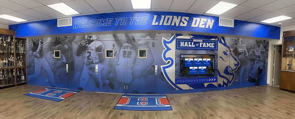
Athletic hall of fame walls representing years of individual and team achievement depend on reliable corridor lighting — a pre-upgrade input rating review ensures new LED fixtures deliver that reliability from the first day of installation forward
Archive and Records Context: Why Lighting Continuity Matters for Historical Trophy Displays
Schools with established trophy case corridors often maintain displays representing multiple decades of athletic achievement. Championship hardware from earlier eras and current-season recognition may share the same case, lit by the same fixture circuit. The continuity of lighting for those historical displays matters not only aesthetically but as part of how the school honors the athletes and teams that came before the current roster.
An LED lighting upgrade planned carefully — with input ratings reviewed, circuit capacity confirmed by a qualified electrician, and dimmer compatibility assessed before purchase — protects that historical display. An upgrade that trips a breaker or causes a dimmer to malfunction during a recognition ceremony does not.
Schools archiving historical athletic photography and records alongside their physical trophy case collections will find the athletic archive photo negative scanning workflow at Digital Yearbook directly relevant to managing the documentary record that physical displays represent. Schools considering how to structure athlete recognition data alongside the physical display will find the athletic awards database policy overview at Awards Display useful context for the digital side of a recognition infrastructure that spans both physical and digital formats.
For recognition programs that include accessible digital display components alongside physical trophy cases, the accessible name audit for hall of fame display interfaces at Hall of Fame Online covers the accessibility audit process that applies to interactive recognition components sharing corridor space with physical cases.

Championship trophy displays representing multiple program generations require planned, reliable corridor lighting — comparing driver input ratings before a lighting upgrade protects the environment that showcases this historical hardware
When to Involve a Qualified Electrician at Each Stage
The input rating review described in this guide produces documentation that informs the electrician’s assessment. It is not a substitute for that assessment. The following table summarizes which stages require qualified electrical review and the purpose of each involvement.
| Stage | Facilities Team Role | Electrician Role |
|---|---|---|
| Specification sheet collection | Gather spec sheets from supplier; document input current, power, PF, and VA for each candidate driver | Not required for documentation tasks; may assist in interpreting unfamiliar specification formats or identifying equivalent parameters |
| Input current and VA calculations | Complete calculations using published values and the formulas in this guide; prepare comparison summary | Not required for calculations; electrician uses the completed summary for circuit assessment |
| DLC and ENERGY STAR verification | Check program databases using model numbers; note listing status and applicable product category in comparison summary | Not required; verification is a database lookup that facilities staff can complete |
| Circuit capacity assessment | Provide comparison summary with estimated total circuit current for each driver option and the fixture count per circuit | Required: confirm continuous-load capacity, applicable NEC sizing guidance, and wiring adequacy for each option in your jurisdiction |
| Dimmer and relay compatibility review | Identify installed dimmer or relay model from device plate or building documentation; include in summary | Required: assess compatibility with driver input type, rated load, and control protocol before purchase decision is finalized |
| Fixture installation | Coordinate access and scheduling; ensure comparison documentation is available to the installation team | Required: all fixture wiring, connection to branch circuit, and energization |
| Post-installation documentation | Retain installed driver spec sheets in maintenance records; note installation date and circuit assignment | Required: confirm circuit behavior at full load, document any anomalies, and provide post-installation verification record |

Athletic corridor installations with multiple case positions and mixed load types benefit from a structured electrician review before LED upgrades — the input rating comparison gives the electrician specific numbers to assess rather than only a fixture count and wattage
Frequently Asked Questions
What is power factor in the context of LED drivers for school trophy case lighting? Power factor is the ratio of real input power (watts) to apparent input power (volt-amperes, or VA) for an LED driver. It describes how effectively the driver uses the current it draws from the branch circuit. A driver with a power factor of 1.0 uses all of the current it draws for actual work; a driver with a lower power factor draws additional reactive current that the circuit must supply but that produces no useful output. For circuit sizing, the input current from the specification sheet — which reflects the driver’s actual PF — is the most directly useful value. Your electrician uses that current figure, not the wattage alone, when assessing circuit capacity.
How is power factor different from LED driver efficiency? Power factor describes the relationship between real input power and apparent input power on the AC supply side of the driver — it affects how much current the driver draws from the branch circuit. Efficiency describes how much of the real input power is successfully converted into useful output: the fraction of input watts that becomes light rather than heat inside the driver. A driver can have high power factor while still converting input power inefficiently. A driver can be highly efficient internally while having a lower power factor if it lacks active power factor correction circuitry. Both parameters appear on specification sheets and both matter; they address different aspects of driver performance and are reviewed separately.
Why does power factor affect my school’s circuit differently than the wattage calculation? A circuit breaker is sized for current in amperes, not watts. A driver with lower power factor draws more current per watt than a high-PF driver because it draws reactive current in addition to the current doing real work. For a single fixture, the difference may be small. For a corridor upgrade adding many fixtures to a branch circuit that also serves digital display panels, AV equipment, or other loads, the difference in input current between drivers of varying PF — at the same wattage — affects how the circuit’s capacity is used. Your electrician can tell you whether the difference is significant for your specific installation and circuit configuration.
Where do I find power factor on a driver specification sheet? Look for a field labeled “Power Factor,” “PF,” or “Input Power Factor.” It is typically in the electrical specifications section alongside input voltage range, input current, and input power. It is expressed as a decimal (0.92) or percentage (92%). If it is not listed, calculate it from input power and input current: PF = Input Power (W) ÷ (Input Current (A) × Supply Voltage (V)). If neither PF nor the values needed to calculate it appear on the sheet, request the data from the supplier before proceeding with the purchase.
Is there a specific power factor that school trophy case LED drivers must meet? No single mandatory PF threshold applies universally to all school trophy case LED driver installations. Applicable requirements depend on jurisdiction, circuit type, and any institutional or district purchasing requirements your school follows. Programs such as DLC and ENERGY STAR establish minimum PF thresholds for listed products in specific categories; drivers that carry current listings in those programs have been independently tested to confirm they meet the applicable floor. The DOE FEMP LED purchasing guidance provides a federal institutional reference for LED product specifications that schools participating in federal programs may find applicable. Your licensed electrician can advise whether any local code or utility requirement applies to your specific installation.
Does power factor affect the heat output inside the trophy case fixture? Not directly. Heat output inside the driver enclosure is primarily a function of conversion efficiency — the fraction of input watts lost as heat during AC-to-DC conversion. Power factor affects how much current the driver draws from the branch circuit, not what it does with the real power internally. An inefficient driver generates more heat per watt of output than an efficient driver, regardless of PF. Because trophy case enclosures often have limited airflow, driver efficiency is an important companion specification to PF when evaluating drivers for enclosed case structures. Review both parameters from the specification sheet and discuss thermal environment with your electrician.
What is total harmonic distortion (THD) and how does it relate to power factor? Total harmonic distortion measures the harmonic content of the driver’s input current — the percentage of drawn current that consists of frequencies other than the fundamental 60 Hz AC frequency in North America. High THD is related to low power factor in LED drivers without active power factor correction: both can arise from the driver drawing current in sharp pulses rather than continuously across the AC cycle. Drivers with active PFC stages that improve power factor typically reduce THD at the same time. Both parameters appear on specification sheets and both affect how the driver interacts with the building’s electrical system, particularly in installations with many drivers on a shared circuit or sub-panel. Include any listed THD value in the comparison document you provide to your electrician.
Should the driver specification review happen before or after contacting an electrician? Facilities staff can complete the specification sheet collection, input rating calculations, and comparison summary (Steps 1 through 5 in this guide) before the first electrician conversation. Having a comparison document with specific input current, apparent power, and PF values for each candidate driver gives the electrician concrete numbers to assess rather than brand names and wattage estimates. The electrician’s review of circuit capacity, dimmer compatibility, and wiring adequacy (Step 6) should occur before the purchase decision is finalized — not after fixtures have already been ordered.
When should our school consider digital recognition displays alongside the physical trophy case maintenance program? When LED upgrade planning, driver input rating reviews, and circuit assessments are consuming facilities resources on a recurring basis, many schools evaluate whether their recognition program goals can be met more sustainably through a combination of physical cases and digital displays. Physical cases continue to hold championship hardware and retired jerseys that require no lighting maintenance to exist — they require maintenance to remain visible. Digital recognition displays handle current-season achievements, alumni archives, and interactive content independently of physical case lighting infrastructure, without the circuit sizing, PF comparisons, and dimmer compatibility reviews that a physical fixture upgrade requires. The two approaches complement each other; the question is which content is best served by each format.
A school trophy case LED power-factor review is a documentation task, not an advanced electrical procedure. Locating the input current, apparent power, and power factor values in supplier specification sheets, calculating any values not explicitly listed, and compiling those figures into a comparison summary that a licensed electrician can assess against the corridor’s actual circuit capacity — that is work facilities staff can complete before a purchase decision is made. It takes the electrician conversation from “we want to install these fixtures” to “here is what each option draws from the circuit, and here is the fixture count.”
The recognition corridor that holds a school’s championship trophies, its hall-of-fame plaques, its retired numbers, and its current-season hardware depends on that planning to function reliably. An upgrade that works correctly from the first day of installation — because input ratings were reviewed, circuit capacity was confirmed, and dimmer compatibility was assessed before a purchase order was signed — serves every athlete whose recognition the corridor displays.
See How Schools Build Recognition Programs Beyond the Trophy Case
If your facilities team is managing LED upgrade planning for trophy case corridors, Rocket Alumni Solutions can show you how schools are extending their recognition programs with cloud-managed digital displays. Interactive touchscreens with remote content management, unlimited recognition capacity, WCAG 2.1 AA accessibility, and factory-calibrated display hardware — no input current calculations, no PF comparisons, and no circuit sizing review required for each recognition update. See the platform in a live demo configured for your school's athletic recognition program.
Schedule Your Demo